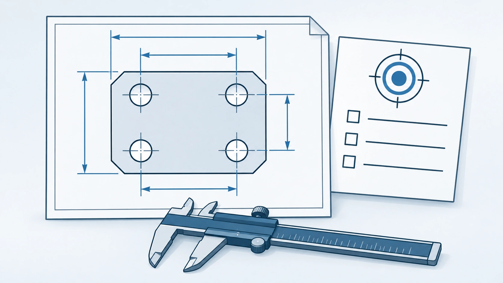
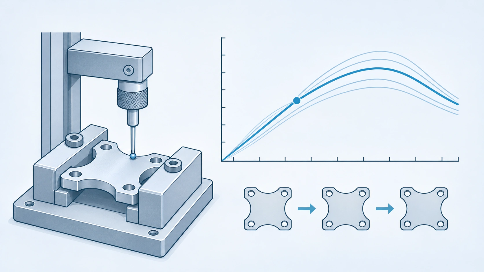
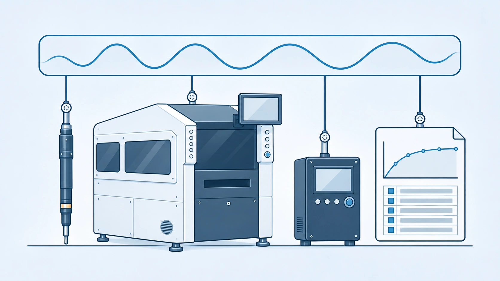
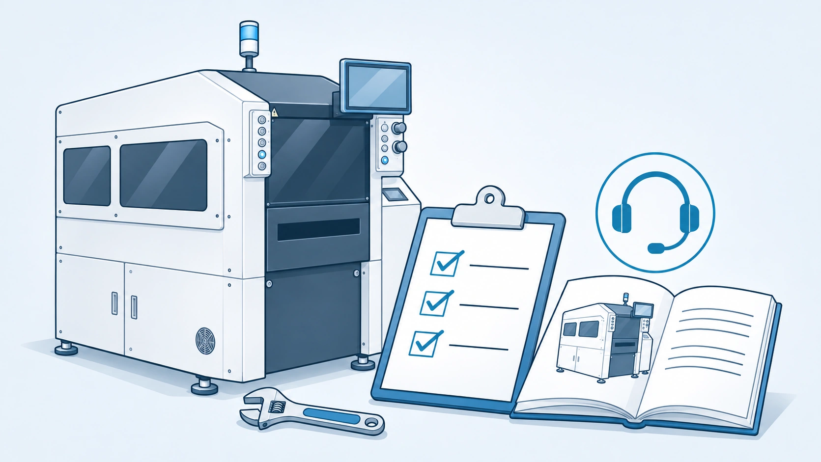
Understand industry processes and connect product capabilities. Together with customers, we define solutions starting from manufacturing needs.
ELECTRONICS
01 / 04
Precision meets flexibility.
Bring tightening, assembly, SMT carrier handling and testing into a coordinated process chain for fast-changing products and precision assembly requirements.
Let precision assembly be integrated into daily production.
Faced with the demand for multiple varieties of electronic products, repeated assembly and process turnover, tightening tools, operating stations, flexible assembly and carrier circulation will be planned accordingly. Starting from one work station also leaves room for adjustment for subsequent product changes.
01 / PRECISION TIGHTENING
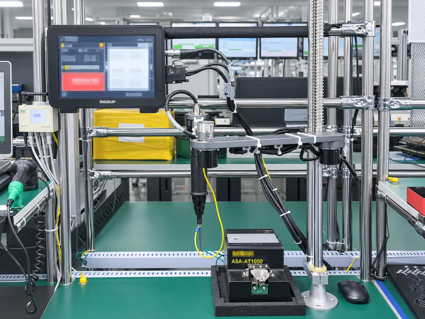
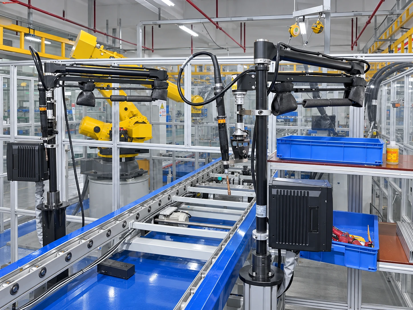
Align the tools with the workstation around the workpiece.
Starting from small connectors and assembly positions, we combine tool support, feeding, positioning and display to arrange operations, taking into account the convenience of personnel operation and the connection of processes.
Manual assistance · Workstation configuration
Auxiliary tightening and workpiece positioning
Concentrate straight-handled tools, auxiliary supports and positioning tooling in the operating area, and coordinate with adjacent conveyor arrangements to pick up, place and tighten, to facilitate repeated operations and on-site inspections.
Material supply matching · Operation confirmation
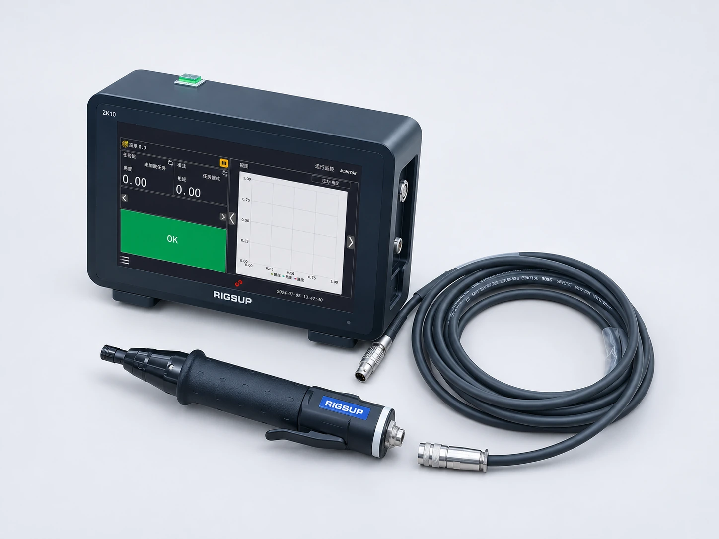
Screw Feeding, Tools & Operator Display
Evaluate the combination of screw feeders, tools, and control displays around screw specifications, feeding methods, and workpiece positions to reduce the inconvenience of back-and-forth retrieval and status confirmation.
From manual assistance to equipment lock-in payment.
Discuss the suitable form of screw fastening equipment based on the product batch size, workpiece size and front and rear processes.
SL-A
Offline screw fastening equipment
It is suitable for organizing product input and take-out at independent workstations, and arranging production in combination with tooling, material supply and program preparation.
SL-B
Online/offline screw fastening equipment
Combined with the on-site conveying direction and product circulation method, evaluate the configuration that can be used independently or connected with the previous and subsequent processes.
SL-D
SCARA screw fastening equipment
For multi-position locking tasks, prototype verification is carried out based on the workpiece posture, reachable range and safe operating space.
02 / OPERATION & PROCESS
Provide prompts for steps and make the process checkable.
Consider putting tool use, operation displays and auxiliary supports in the same workstation to facilitate personnel to view tasks, check processes and handle exceptions. The specific display content and recording function are confirmed according to the configuration.
Job display · Program switching
Operation steps and workstation display
Set the operation interface in an area visible to personnel, and organize operation prompts based on product and task configurations to facilitate changeover preparation and step verification.
Process records · Exception review
Control interface and result confirmation
Arrange a control display near the tool, conduct a review based on the fastening results and process records, and accumulate evidence for process review and problem location.
Support package · Convenient to use
Auxiliary support and operating space
Combining the weight of the tool, the position of the connection point and the posture of the person, configure the reaction arm and balance support, and coordinate the cable path and daily inspection location.
03 / ASSEMBLY & MATERIAL FLOW
Plan assembly, turnover and process connections together.
Combined with flexible assembly equipment, SMT carrier disassembly and assembly, and pallet transfer applications, production is collaboratively organized around product families, supplies, carriers, and front and rear equipment.
Flexible assembly·Preparation for changeover
Flexible assembly and high-mix production
For repetitive pick-and-place and assembly tasks, evaluate the scope of work based on product, auxiliary materials and tooling conditions. When changing models, prioritize the materials and configurations that can be used to reduce repeated preparations.
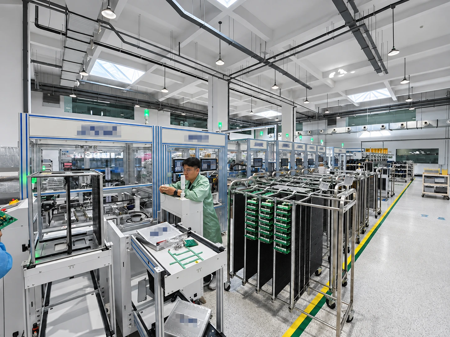
SMT process·Carrier turnover
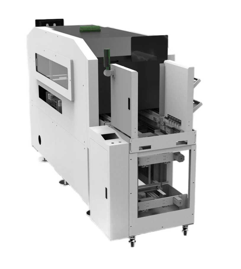
Automated SMT Carrier Assembly & Disassembly
Evaluate the disassembly and assembly process around carrier covers, buckles, product protection and material collection requirements, and connect carrier turnover with the production rhythm of front and rear equipment.
Video screen arrangement · Logistics collaboration
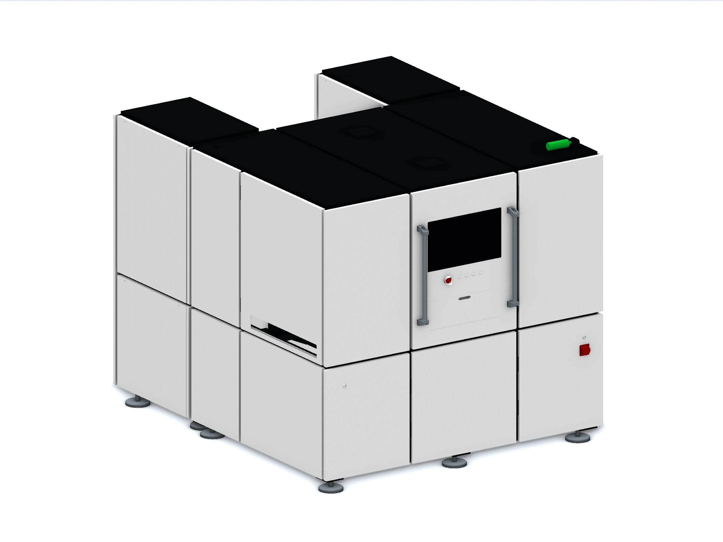
Material tray transfer and work station docking
The video data shows the tray transfer, connection and equipment side flow scenes. Plan the connection between workstations based on the form of incoming materials, docking locations, and upstream and downstream needs.
Prepare samples, connectors, assembly sequences and quality requirements, and clarify the scope of operations suitable for automation.
Supply and turnover
Check the connection conditions of screw feeding, pallet, carrier, input and removal methods, and front and rear equipment.
Changeover & Reuse
Sort out product families, procedures, tooling and existing data, evaluate reusable scope, and reduce repeated preparations.
long term use
Incorporate operational training, exception handling, maintenance inspections and record handover into the plan to facilitate subsequent use and improvement.
The pictures are organized based on the actual on-site data provided by the company, unifying the direction, proportion and tone, and processing relevant logos and production information. Different pictures show different workstations; the adaptation range, functions and delivery requirements are verified and confirmed based on the actual workpiece.
RAIL TRANSIT · PRODUCT PRACTICE
Make signal testing closer to on-site needs.
From portable boxes to board modules and rack-mounted equipment, the product form is selected based on the object to be tested and how it is used, and wiring, operation, status verification and subsequent maintenance are all included in the plan.
01 Portable test box02 Signal interface board03 Rack-mounted equipment
01Portable testing
Portable General Purpose I/O Test Box
Around the input and output signals, terminal blocks, operation buttons and status indicators are centrally arranged to facilitate on-site wiring and item-by-item verification.
02Boards and modules
Signal interface boards and modules
Organize interfaces, status indicators and operating positions in the form of boards and front panels, and confirm channel definitions and access methods based on the object under test.
03rack equipment
Rack-mounted signal test equipment
Operations and indication locations are centrally presented through multiple panels, providing equipment form reference for multi-channel wiring, status checking and test configuration.
04product portfolio
Real shots of portable test box products
Similar cabinets adopt centralized operation panels and portable structures; according to different signal and wiring requirements, the panel layout and configuration are confirmed separately.
05Equipment appearance
Rack equipment oblique side view
Display the rack appearance, handles and module layout to facilitate discussion of equipment handling, placement and on-site usage conditions.
06Device perspective
Rack equipment rear view
Supplement the appearance of the chassis back and mesh enclosure, and confirm the wiring, inspection and maintenance locations based on the on-site space.
APPLICATION FIT
First clarify the test tasks, Confirm the product configuration again.
Organize the measured object, wiring definition, channel number and electrical conditions, and check the terminals and operation methods.
Operation and verification
Confirm operation sequence, status indication, test rules and recording requirements in combination with on-site steps.
Verification and delivery
Confirm the adaptation range through samples or on-site conditions, and incorporate wiring data, operating training and maintenance requirements into delivery.
The picture is provided by the company, and the customer's logo has been mosaic processed. Specific functions, signal ranges and test indicators are confirmed according to the project plan and verification results.
AUTOMOTIVE & NEW ENERGY · IN PRACTICE
Let tools, workstations and personnel cooperate with every tightening.
From component assembly to large workpiece operations, intelligent tightening tools, auxiliary supports, workpiece positioning and on-site operations are combined. Choose the appropriate workstation form based on connection requirements, accessible space and production cycle time.
01 / PRECISION ASSEMBLY
From a single connection point, to continuous assembly stations.
In desktop or automated workstations, fastening operations are arranged based on workpiece positioning, tool support and operation display, taking into account manual use and equipment integration.
Desktop workstation · whole group layout
Multi-station auxiliary tightening
The desktop workstation centrally arranges tools, auxiliary supports, feed materials and workpiece positioning, making it easy to arrange repeated operations and coordinate with adjacent workstations.
Manual assistance · Tool matching
Tool support and operating tips
Arrange straight-handled tools, balance supports and work displays within the operating range to help personnel confirm positions and check steps.
Automated jobs · Unit integration
Automated tightening unit
Combine the actuator, tooling, transportation and safety enclosure to organize and lock the workstation; specific actions, connection requirements and exception handling are verified according to the product.
Workstation details · Daily use
Feeding, positioning and tool coordination
From tool hanging, material preparation to tool placement, convenience of access, working space and material replenishment inspection are all considered.
02 / ASSISTED TIGHTENING
When facing large workpieces, consider the working space together.
Combined with the location of the connection point, tool weight and reaction force requirements, configure the reaction arm and auxiliary support. Incorporate personnel operation, workpiece turnover and display position into the planning to serve the assembly needs of large workpieces related to complete vehicles and new energy sources.
Matching form · Combination according to working conditions
Various lever arm and support configurations
Different shapes of auxiliary arms, end tools and control packages provide an intuitive reference for discussing coverage, operating postures and on-site installation.
BUILT AROUND THE WORKPIECE
Let the tools arrive, It also makes operation smooth.
Evaluation coverage around workpiece dimensions and connection point distribution
Check tool posture, socket space and cable routing
Taking into account support, reaction force, personnel access and maintenance positions
On-site personnel use tools with the help of support arms to operate and confirm around the connection points of large workpieces. Adaptation can be evaluated in conjunction with new energy-related assembly tasks.
Workstation connection and support configuration
Bilateral tool and conveyor coordination
The support arm is arranged near the conveying station, and the reachable range of the tool and the parking position of the workpiece are considered together to facilitate the organization of operations on both sides.
Whole line coordination · On-site layout
Fastening station and material flow
Place tools, roller conveyors, and surrounding material areas in the same work layout, and clearly define pickup, placement, parking, and inspection locations.
Supporting work stations · Human-machine collaboration
Lift arm, tooling and display coordination
Combine auxiliary support, positioning tooling and on-site display in the large workpiece station to discuss operation confirmation, changeover and usage space.
03 / COMMISSIONING & TRAINING
Make on-site use part of the delivery.
Check tool settings, working postures, personnel operations and abnormality confirmation in real workstations, and hand over operational training and daily maintenance requirements together.
On-site debugging·Usage confirmation
Work station debugging and operation confirmation
Engineering and on-site personnel communicate around tools, workpieces and workstations, confirm operation methods and equipment coordination, and prepare for daily production.
Operational training·Experience handover
Face-to-face operational training
Explain the steps of use based on actual tools and tooling, and check the methods of picking and placing, positioning, fastening and result confirmation.
APPLICATION PLANNING
Starting from the connection requirements, Plan the workstation completely.
Organize connectors, materials, fastening requirements and samples, confirm tool form, bits or sleeves and verification methods.
Operation and rhythm
Evaluate the work station arrangement based on the distribution of connection points, personnel posture, tool support, feeding and conveying methods.
Process and Records
Plan workpiece identification, operation steps, results and curve records, and abnormal review according to project requirements, and integrate the existing manufacturing system to confirm the interface.
Delivery and use
Incorporate sample verification, workstation debugging, operational training, maintenance inspections and subsequent changeovers into delivery evaluation.
The on-site pictures are provided by the company and have been modified in terms of direction, composition and tone, and the relevant logos and production information have been anonymized. The pictures respectively show different workstations and equipment forms; specific adaptation, configuration and acceptance requirements are subject to project verification.
ADVANCED MANUFACTURING · ENGINEERING IN PRACTICE
From critical connections, to complete manufacturing processes.
Integrate intelligent tightening, auxiliary support, flexible assembly, inspection and industrial software into actual processes. Starting from the convenience of using a single workstation, it gradually connects equipment, materials and process records to serve the manufacturing needs of multiple varieties and complex workpieces.
01 / PRECISION CONNECTIONS
When facing complex workpieces, consider connection quality and operation together.
Combine the connectors, fastening requirements, space and working posture to configure suitable tools and auxiliary supports. Confirm accessibility, operation methods and process judgment basis through prototypes and on-site verification.
Aircraft Manufacturing · Real Application
Tool applications in aircraft manufacturing
The aircraft manufacturing site shows how people use tools to access the connection points of the aircraft body. Focusing on the structural space and connection requirements, evaluate the tool shape, end matching and operating posture.
Large workpiece assembly · Lift arm assistance
Auxiliary fastening of large workpieces
The cooperation of tools, lever arms and workpieces has been demonstrated on-site related to automobiles and new energy. For large components, coordinate coverage, reaction support, access and cable routing.
Every connection point has a verifiable basis.
Organize parameters, operation steps, fastening results and process curves around process requirements; plan and record combined with workpiece identity and abnormal review requirements to facilitate quality analysis and subsequent improvements.
Allow existing investments to adapt to subsequent product changes.
Starting from specific tasks such as repeated picking and placing, assembly of auxiliary materials, and loading and unloading of components, the product family and automation boundaries are clearly defined. Discuss the reuse scope of procedures, tooling and supplies during the planning stage to reserve space for subsequent changeovers.
Flexible assembly·Multiple variety preparation
Flexible assembly and process adaptation
The flexible assembly site displays equipment, material trays and peripheral accessories. Evaluate the task scope based on the actual product and assembly requirements, and incorporate incoming material preparation, first-piece verification and daily inspection into the plan.
Assembly unit · Phased integration
From unit operation to process connection
The electronic product assembly unit demonstrates the cooperation of tooling, actuators, on-site displays and transportation. Independent units are organized according to process requirements, and front and rear equipment can also be connected in stages.
Put assembly, testing and material flow back on the same planning diagram.
First understand product flow, material flow and information flow, and then confirm the number of equipment, cache, manual workstations and abnormal flow directions. Organize production capabilities in modules to take into account current use and subsequent adjustments.
Assembly line·Process organization
Assembly process and material turnover
The assembly line shows multiple work units and board turnover areas. Arrange the processes around loading, fastening, manual assembly, testing and storage, and coordinate on-site rhythm and personnel collaboration.
Testing line · Quality basis
The detection section cooperates with the sending and receiving board
The flying probe inspection site demonstrated the cooperation between multiple test equipment and the sending and receiving board unit. According to the board, test tasks and time requirements, plan the detection section configuration, transfer and result review.
Transform engineering capabilities into sustainable use value.
01
Be more prepared
Starting from the sample, process and site conditions, the equipment configuration, verification content and acceptance basis are clarified.
02
Easier operation
Combined with personnel posture, tool support, display position and maintenance access, the workstation is convenient to use.
03
Experience can be used
Precipitate procedures, tooling, operating points and quality records into data to provide reference for similar products and subsequent adjustments.
04
Invest in the full cycle
Comprehensively evaluate the impact of changeover, training, maintenance and shutdown, and judge the long-term use value based on actual working conditions.
FROM VALIDATION TO DELIVERY
Verified from samples, Go to the scene and use it stably.
Confirm connection and assembly tasks, product scope, quality requirements and site conditions, and clarify the division of labor and equipment.
Carry out sample verification
Use typical workpieces to check tool accessibility, positioning protection, assembly results and detection methods to form the basis for the plan.
Collaborating devices and data
Plan transportation, control, workpiece identification and process recording interfaces according to the project, and clarify the collaboration boundaries of front and rear equipment and existing systems.
Handover experience
On-site debugging, acceptance, training, maintenance inspection and exception handling data will be delivered together to support subsequent operation and adjustment.
This page summarizes the company's existing aircraft manufacturing, automobile and new energy, electronic assembly and testing site data, and describes the relevant processes and engineering capabilities respectively. It does not mean that the same project includes all units. The modified and anonymized version of the picture will be used; the specific functions, adaptation range and acceptance requirements will be verified and confirmed according to the project.