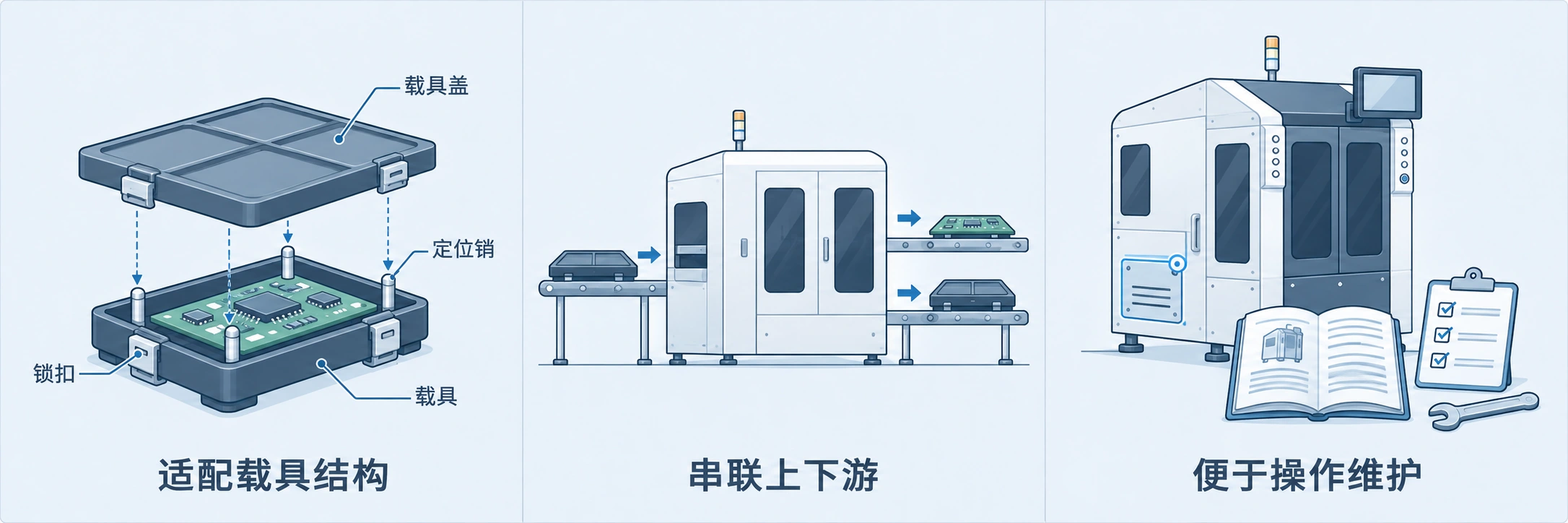
Adapt to actual carriers
Complete sample evaluation based on spring fixtures, synthetic stone double-sided tape fixtures, FPC soft board fixtures, etc., combined with cover plates, buckles, and product protection requirements.
SMT CARRIER AUTOMATION
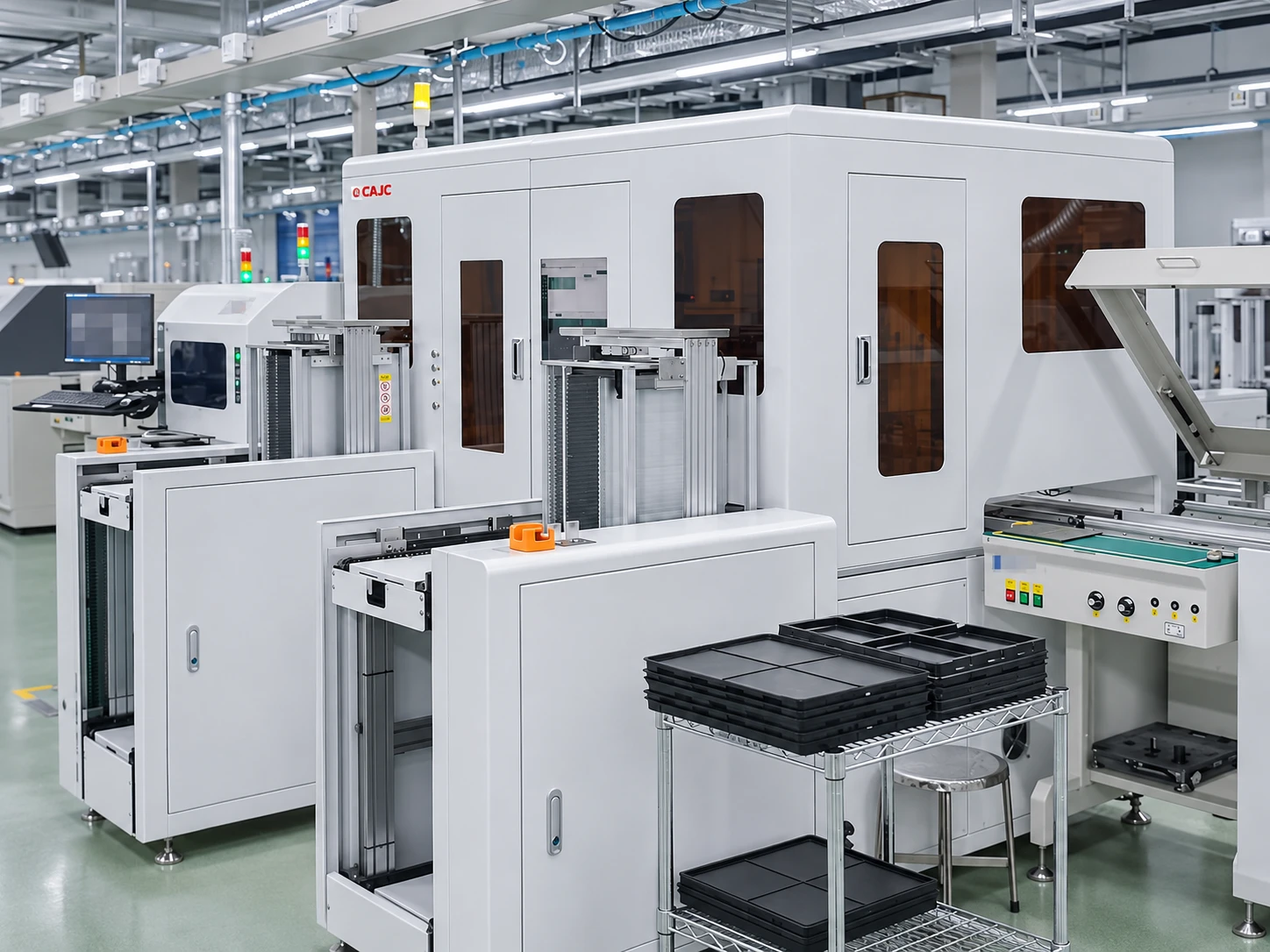
Connect PCB loading, carrier assembly, separation and circulation on single- or dual-lane SMT lines. Reduce repetitive manual handling and organize changeovers, operation and upstream/downstream coordination.
Discuss Carrier & Line Requirements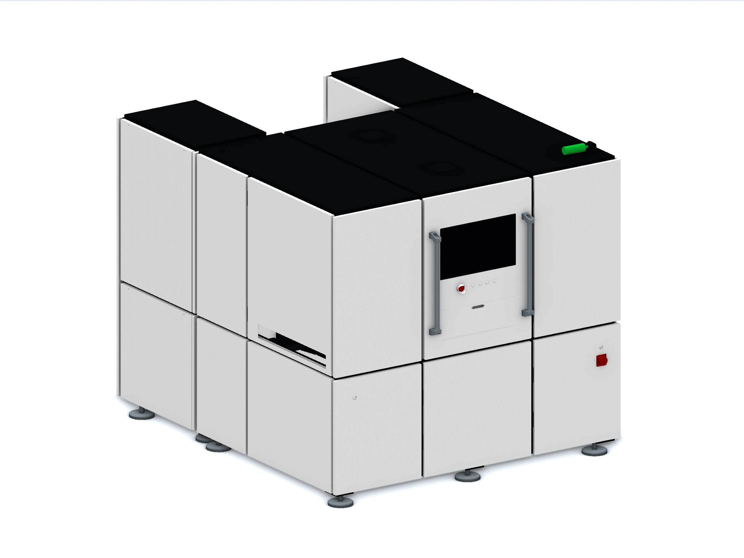
FROM REFLOW TO RECIRCULATION
Suitable for SMT manufacturing scenarios of mobile phones, wearable electronics, notebooks, tablets and other products. Focusing on the carrier printing, patching and reflow processes, we plan the loading, disassembly and subsequent turnover of PCBs and carriers.
The equipment can be connected after AOI/NG buffering and other processes; the specific station position, incoming material classification, turning, fastening and framing steps are combined according to the production line process.
Check products, carriers and incoming material directions, and classify or identify by project configuration or barcode.
Complete PCB pick-and-place, split or load actions around the actual carrier.
Combine turning, fastening and framing steps according to process requirements.
Connect subsequent transportation, buffering or collection to ensure orderly flow of materials.
PRODUCT CAPABILITIES
Complete sample evaluation based on spring fixtures, synthetic stone double-sided tape fixtures, FPC soft board fixtures, etc., combined with cover plates, buckles, and product protection requirements.
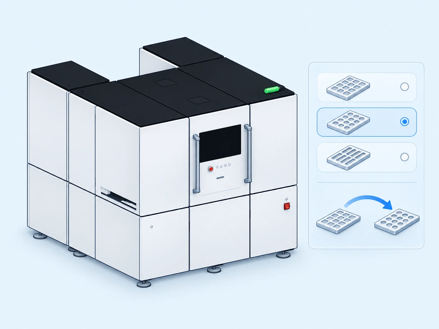 02
Organize product switching through graphical operation, program configuration and changeover guidance; it can be combined with quick-change tooling and offline commissioning to reduce repeated preparations.
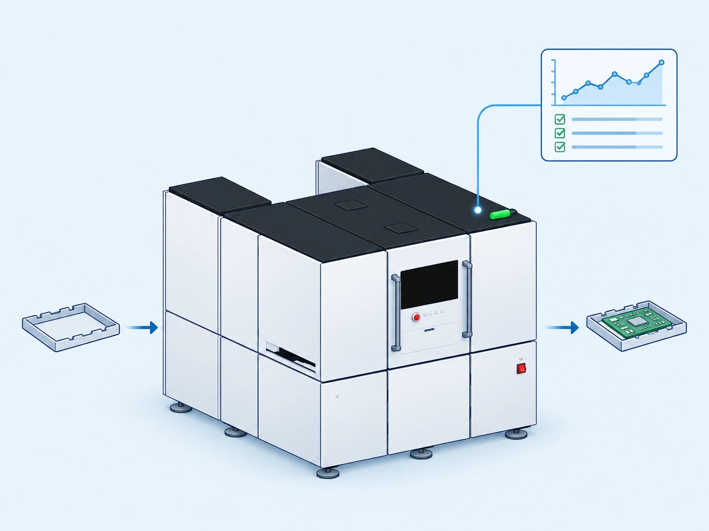 03
Supports single/dual track solution and standard SMEMA signal docking, and plans full line collaboration based on barcode recognition, MES interface and material collection requirements.
EVERYDAY CONVENIENCE
Graphical interface and high/low authority management make it easy to distinguish daily operations and process settings.
Organize product switching with program configuration and changeover guidance, and incorporate tooling verification and first-piece verification into the preparation process.
Evaluate adjustable tooling, quick-change methods and offline commissioning based on product families, and strive to reduce repeated adjustments online.
Plan the collection of materials by combining incoming materials, caching and transportation methods; the docking machine or AGV can be selected according to the project.
CARRIER HANDLING · PRODUCTION PREPARATION
Focusing on the actual status of the PCB, carrier and cover, consider loading, product protection, changeovers and collecting in the same usage path.
Plan the loading according to the PCB, empty fixtures in different directions and material preparation methods to reduce repeated picking and sorting on site.
Combined with the carrier temperature after passing the oven, PCB appearance and anti-static requirements, confirm the contact material, grabbing conditions and placement method.
Combined with adjustable tooling, quick-change configuration and offline commissioning, product information and key locations can be checked in advance to reduce repeated online preparations.
The collection of materials is organized according to stacking, caching and transportation habits, and can be planned in conjunction with the optional pallet machine or AGV.
Confirm the implementation method according to the specific configuration and verify it with the actual carrier. The cycle time, line change time and quality indicators are agreed upon based on the sample and site conditions.
JCZ-S2C-SMT-2001 · CONFIGURATION REFERENCE
The JCZ-S2C-SMT-2001 in the brochure provides an alternative device configuration reference. Organize operations around single/dual-track SMT production lines, combining PCB and blank fixture feeding, graphic operations, and receiving material buffering.
Customers can put forward requirements from carrier adaptation, tooling preparation, upstream and downstream interfaces and operating habits, and then confirm the configuration and acceptance content through samples.
| Selection items | JCZ-S2C-SMT-2001 brochure reference | Confirmation points |
|---|---|---|
| Carrier Dimensions | Minimum 150 × 150 × 1 mm; Maximum 300 × 210 × 3 mm | Listed by length × width × height, combined with cover, buckle and product protection requirements for verification. |
| Equipment appearance | 2000 × 1500 × 1800 mm | The brochure indicates that the plate collector is not included and can be customized; please confirm with the overall envelope dimensions of the CZ2-00 model on this page. |
| Orbital height | 900 ± 50 mm | Confirm based on the conveying height of front and rear equipment and on-site installation conditions. |
| Air source requirements | 0.6 MPa | Gas supply and other utility conditions are subject to delivery configuration. |
| Machine weight | approx. 900kg | Used for preliminary transportation and load-bearing evaluation, and final verification according to actual configuration. |
| Interface and operation | Standard SMEMA interface; RVS software, graphical interface, rights management, changeover guidance | Requirements such as barcode, MES, receiving material buffering and AGV need to be confirmed on a project-by-project basis. |
This table only applies to the models in the brochure provided and cannot be directly applied to other appearances or configurations on this page. The cycle time and line change time listed in the brochure have different configuration calibers, and the actual indicators are subject to the verified project plan.
CZ2-00 · EQUIPMENT VIEWS
Based on the 3D model rendering of the device, it shows the overall appearance, bilateral frame and control surface layout. Click on the image to enlarge it.
The black top plate and gray-white sheet metal shell present the overall appearance of the device.
View the equipment frame and operating opening from the oblique side.
Complement the shape and spatial relationship in the other direction.
Show the side where the display, emergency stop and main power switch are located.
Product three-dimensional model rendering; specific equipment appearance, configuration and delivery scope shall be subject to the project plan confirmed by both parties.
OVERALL DIMENSIONS
Dimensions are measured according to the overall envelope of the current STEP model, including the receiving frame, foot cups and light fixtures in the model. Maintenance passages, door openings and carrying spaces must be reserved separately; the final equipment layout shall be subject to confirmation.
CONFIGURATION
Start by confirming samples, product protection, material supply and receipt methods. The size range, cycle time and line changeover time will be agreed after verification under specific working conditions.
Submit selection requirementsREAL-WORLD APPLICATIONS
The equipment has entered manufacturing sites in different countries. The following photos are provided by the company, the project country has been confirmed, and the client's name is displayed anonymously.
TÜRKİYE · PROJECT SITE
This photo of two people in front of the equipment records the application scenario of the product at the Turkish customer site, and also provides a real on-site reference for overseas project communication.
From the appearance of the equipment to the layout of the site, we pay attention to the connection between the equipment and the actual production line conditions. For similar needs, communication can be carried out on an item-by-item basis around carrier adaptation, process interface, operation and follow-up support.
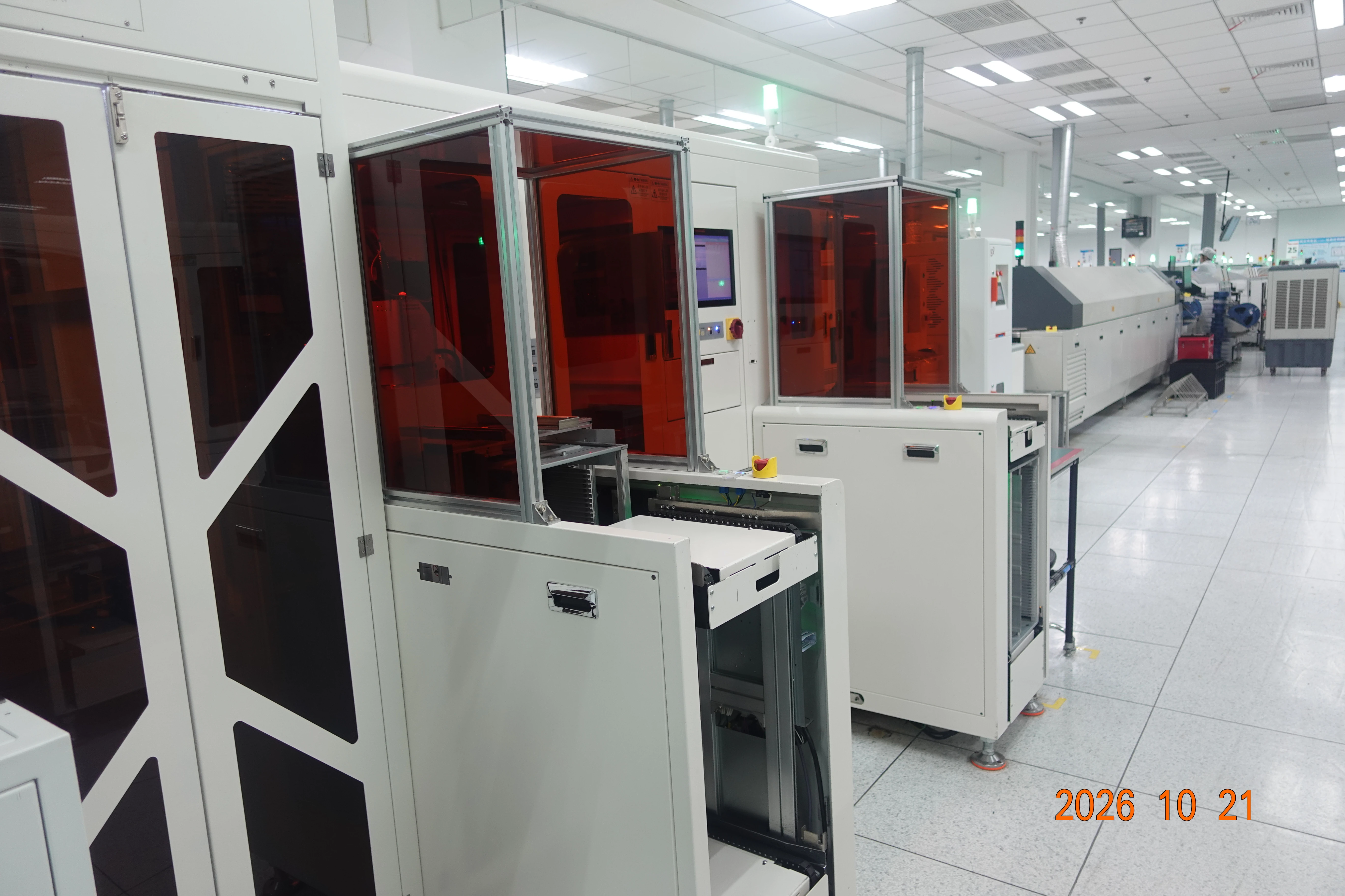
Customer names and personnel names are displayed anonymouslyUnderstand SMT project practicesThe on-site arrangement of automatic carrier disassembly and assembly equipment and front and rear conveyance and collection units in the customer's production line.
On-site real shots show the disassembly and assembly station and the bilateral feeding and receiving units, providing reference for similar process configurations.
VALUE OVER TIME
Leave repeated disassembly and turnover to the equipment, and evaluate the room for improvement in labor input and on-site operation burden.
Accumulate program, tooling verification and sample verification records to provide reference for switching between similar products.
Plan the equipment interface, material receiving method and data requirements together to reduce repeated confirmation work between processes.
Evaluate investment recovery based on actual production capacity, order changes, labor, maintenance and downtime costs; income depends on carrier adaptation and on-site use conditions.
CUSTOMER STORIES
ENGINEER YOUR NEXT